Sunday, September 26, 2010

WS8 primary & secondary ignition patterns


toyota soarer 1994

Primary Voltage Patterns::
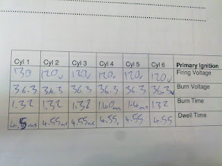
The primary pattern shows us how long it is grounded for, how much voltage is used to cross the gap (burn voltage) and how long it takes to cross (burn time) This is good to help with diagnosis because it shows how strong the burn voltage is and the time it takes to cross. (a good way is string theory) higher burn voltage short burn time, low burn voltage long burn time.


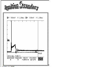
Secondary Voltage Patterns::
The graph shows us a similar pattern as the primary jus the firing voltage isnt as high but the burn time is the same. In the secondary pattern it shows At snap acceleration you notice straight away the burn voltage goes down and it has a longer burn time. This is as expected

NOTE: The primary curcuit colapses on it self inducing a voltage in the secondary of similar voltage. same pattern.

WS7 exhaust gas analysis

mazda 323 wagon 2000


Engine idling: cold- CO= 5.8 HC= 521 CO2= 11.52 O2= .28
This is a rich mixture causing high CO there is too much fuel and some is unburnt causing high HC CO2 level is good for emissions but not the car and O2 levels are good indicating no oxygen in the exhaust.

Engine idling: warm- CO= 6.970 HC= 493 CO2= 10.78 O2= .19
The CO reading indicates low oxygen because the O2 level is low also the HC are low indicating fuel is getting burnt. The CO2 reading is good but bad 4 global warming.

Engine warm 2500rpm: CO= .4 HC= 123 CO2= 14.6 O2= .47
These are good readings. similar to idle so it indicates that even reving it the car still functions okay under load.

Idle lean mixture: CO= .07 HC= 230 CO2= 11.88 O2= 4.9
The CO reading tells us that its a lean mix because it matches up with the O2 indicating there is heaps of oxygen and a little bit high HC means some unburnt fuel but thats caused by too much oxygen and the flame cant get across.

Blipping idle: CO= 3.349 HC= 1188 CO2= 9.09 O2= 9.34
These readings are no good. The CO indicates too much fuel which should lead to a low oxygen reading but it doesnt indicating we have an air leak somewhere. Heaps of HC meaning fuel isnt getting burnt an the low CO2 is related to heapz of CO and O2 not joining together.

Disconnected 1 spark plug: CO= .157 HC= 2672 CO2= 7.28 O2= 11.03
The O2 and CO relate meaning this should be a lean mix but the HC levels are so high which means there is unburnt fuel. This is caused by the 1 spark plug not firing (weak spark) leaving unburnt fuel behind.

Disconnected injector harness: CO= .068 HC= 188 CO2= 6.94 O2= 11.72
With the 1 injector not functioning the CO show that there is not enough fuel (lean) the HC shows theres a lil unburnt fuel which maybe caused by all the extra oxygen

under load: CO= .550 HC= 195 CO2= 14.02 O2= 1.58
CO showz the mixture is a lil lean but the HC also tells us that most of the fuel is getting burnt and the O2 readings are good meaning theres no air leaks or extra air and the CO2 are good showing good emissions but bad for the economy

WS6 O2sensor on vehicle


Toyota soarer 1994

On the vehicle I tested the oxygen sensor was located on the exhaust manifold. The oxygen sensor has one black wire which is a signal wire. The oxygen sensor is a zirconia switching sensor. I back probed the Oxygen sensor and attached an oscilloscope and got a signal. When revving the vehicle at 2500rpm the signal voltage reached 1volt and the lowest was 0.03volts. It has 9 cross counts. Its cycling normally.

WS5 scan tool diagnostics


mazda capella wagon:
Trouble codes found were 100 & 110 MAF & IAT respectively. These components wern't working properly. Using the scan tool the codes that changed were IAT 19.85degrees & MAF 0volts. Using the scan tool information I did a visual inspection and found air flow cold box meter sensor not properly pluged in and MAF sensor plug was also not plugged in properly. To repair the fault I plugged both connector bak in and now working fine. (good readings).
Recheck Data:
IAT 25.46degrees & MAF 1.87volts
Clear codes: removed scan tool for a couple minutes then plugged it back up and searched for codes. No fault codes found.

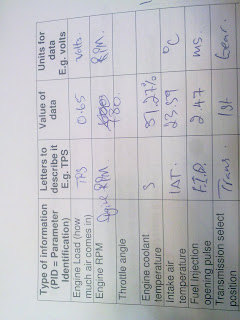
The importance of live data is that you can get information about the can then and there when its operating. For example you might get an O2 reading of 0volts and you might thick thats ok but when you check live data itl stay O2 sensor open loop and the voltage should be .45v.

The need for parameters when checking live data is that all signals come in and are calculated then an outcome is made, if one signal was faulty it could be affecting another components so we have parameters so we can monitor an idividual component.

A scan tool can aid you when fault finding because its current data and its telling you exactly whats happening and the fault codes it gives is a good indication on what and where the fault might be. (always start from the battery)

WS4 fuel pressure & flow

nissian primera 1992

There are no leaks. With the key on engine off the fuel pressure is 264kpa. On idle for a couple of minutes the fuel pressure is 260kpa. With the engine idling and then the fuel line is clamp the fuel pressure rises to 490kpa. When the vacuum line is disconnected and plugged on idle the fuel pressure rises to 310kpa. The rest fuel pressure was recorded at 250kpa after the engine is truned off and fuel pressure was watched for 5 minutes. The flow of fuel was 2.2l a minute.
After test equipment ws taken off and fuel lines hooked back up properly I check for leaks before it was turned on and after engine was running.
It is important to know a vehicle fuel pressure/flow to ensure that fuel is reaching the injectors and tat the right pressure so the car won't be running rich/lean.To much pressure could cause a hose to burst and to little could cause low combustion. Faulty fuel pressure regualtor could cause to much fuel pressure in the fuel rail and cause the car to use to much fuel and it won't be economical.

WS3B dual trace patterns

toyota 4A-FEMAP against Injectors:
As the MAP voltage increases the dwell time for injectors increase also. Therefore the injector increases more fuel due to more air entering the intake manifold. If the MAP voltage doesn't increase and the injectors increased in frequency the engine will run rich use heaps of fuel and poor emissions. (poor emissions is bad for the economy)

RPM against Injectors:
As the cam speed increases the dwell time will increase and the injectors will increase in frequency. If the cam speed increased the engine load will increase also and if the injectors stayed at the same frequency (1ms) you would get a poor combustion (weak) and it may even be early combustion and result in poor performance and eventually damage the engine.

Oxygen sensor against Injectors:
The oxygen sensor fluctuates at idle. As the engine RPM increases the fuel increases in the injectors. As more fuel enters the combustion chamber a rich mixture is burnt and a hi number of oxygen partical are left to flow past the O2 sensor. The O2 sensor can affect the injectors by, if the O2 sensor was reading hi oxygen levels the ECU will tell the injectors to lean off the mix therefore the injectors wont be working in relationship properly with the RPM sensor.
With a high voltage at the O2 sensor the engine is running rich.

Ignition primary against Injectors:
On idle the relationship between the two are the frequency that they are operating at stay the same and as the engine revs up both frequencys increases equally. If the ignition primary was out it would affect the injector by not igniting the air fuel mix properly or on time.

WS3A


Map (Analog) 2v 1sec
As the voltage increases the vacuum decreases. so at idle voltage is 2volts and increases from there as engine rpm increases. If there was a fault in this component or circuit it could effect the engine load. For example if there was high resistance (corrosion) in the earth wire itl effect the output voltage because voltage would be used to push through the corrosion to get to earth.

ECT eng cold .720v eng hot .538v
note: slowly decrease voltage as engine warms up. An ECT is a NTC thermistor. As the engine haeats up the signal voltage drops. If there is a fault with this component it could make the vehicle run rich if the signal voltage is high and the engine is hot. This faulty reading is not good for the car. A faulty reading can be caused by a faulty component. you can also get a faulty reading if you have a bad earth.


IAT 2v 10ms
Hot = 1.495v Cold= .5v
This records the air temp as it passes through the intake manifold. low voltage reading is when the air temp is cold. A high voltage is hot air passing through the the intake manifold. If there is a fault with the IAT like a bad earth you could result in in no signal voltage or high signal voltage if the IAT was faulty but stil had continuity.

TPS Closed throttle 5v Open throttle .5v
In the photo for TPS the low voltage reading of around .5v is the throttle closed on idle. As the voltage readings get high this shows us that the throttle is getting more and more open until it reaches W.O.T. If there is a fault with this component or circuit it can result in the vehicle not responding to the drivers intent. Bad resistance in this circuit will cause incorrect signal voltage. eg.. Vs x (R1+ R2) / R2 = Vout (normal equation) If there is extra resistance the equation would be Vs x (R1 + R2 + R3) / (R2 + R3)= Vout which would be different.

MAF digital
This component reads how much air is coming through to the intake manifold. If there is a fault with this component it can effect the engine load. For example if the variable resistor inside the MAF sensor is faulty the incorrect signal will be given or maybe no signal if it doesn't have continuity. For example if the MAF sensor was half open and sending a signal of .6v instead of 1v that .6v signal might tell the ECU to put less fuel in when infact it should be injecting more fuel.

WS3


MAP (digital) 2 volts per division/ 1sec per division.
On idle the vacuum is high and the voltage is low. (as you can see in the photo) As you rev the engine the vacuum becomes low and the voltage increases. (also in labeled diagram).

O2 sensor. The O2 sensor doesn't operate until it is in open loop. (operating temp) When the car is in open loop it starts to function an fluctuates controlling emissions. Also it picks up how much O2 is passing through and tells the ECU if its running rich or lean and compensates next time around.

Injector petrol 20v per division 200ms.
Injectors are actuators and receive a pwm signal from the ECU to tell them when to open and close and how long for. In the photo it shows voltage supply to the injector then at 0volts the injector is earthed (turned on) then a back EMF caused by the quick colapse of voltage then returns to voltage supply. at voltage supply injector is closed.

Idle air control. (ISC solenoid)
This controls air at idle so the vehicle wont stall. Its a constant pattern because its opening and closing. As the car revs higher the frequency that it ocurrs gets faster so the wave form stays the same shape but gets smaller or wider.

RPM (hall digital)
The RPM wave form is digital and it is rectangle shape. All patterns are the same meaning they contantly reach the 0 voltage and the same high (positive) voltage. As the RPM increases the pattern becomes more frequent meaning the the distributor is spining faster and the waveform becomes more narrow.


RPM (Magnetic) 2 volts 20ms. (ckp magnetic)
The RPM wave form is analog even though it doesn't look like this is because the shape of the rotor. This wave form is constant in it shape becauses its spining in a constant circle. As we rev the engine the wave form is still the same shape but becomes move frequent. (as seen in video)

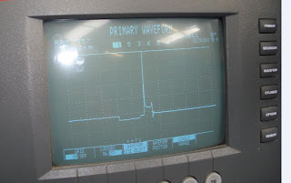
Ignition primary 10v 5ms. (primary waveform)
The low voltage reading is the dwell time (the build up time) then it suddenly collapses an creates a high voltage to cross the spark plug gap. The oscilations after is the burn time then returns to supply voltage.

WS2 flash codes

Toyota corolla FXGT 1992
Results -
Flashes 2 - vacuum sensor signal
flashes 7 - T.P.S

2 - engine load - No signal from vacuum sensor
7 - driver intent - no signal from TPS

As I done a visual inspection under the bonnet I took into account the information I got to help me find the fault and ended up finding a loose connection in the TPS plug and also the vacuum sensor was loose.

When I found where the fault was I plugged both connectors back up.

To clear the codes I disconnect the battery for one minute. I connected the batter back up and rechecked the codes and got 1 flash. I went and check what 1 flash meant and it means normal. The car is fine.

The TPS fault affects the driver and the car wouldn't move or it might alwasy move. The car wouldn't respond to what the driver wants it to do.
The vacuum sensor affects the car operation and would receive and send wrong signals to the ECU. The vehicle wouldn't know if itz under load or not.

Other test you should do is test input, output and signal wires for continuity and for voltage readings.

WS1 petrol fuel injector testing

Mitsubishi galant VR4 1996
I used a screw driver and the injector was OK. The battery voltage was 12v
Results:
Cyl1 12.2v
Cyl2 12.4v
Cyl3 12.3v

When using a LED tester all flashes were acceptable on idle. When revved flashes got so fast it seemed like the LED tester was perminately on but it wasn't. Testing injectors with a LEd tester is a good test but it isnt accurate enough. All it tell us is its opening and closing thats all, not for how long which is what we're looking for.

When using the multimeter set to duty cycle all 3 cylinders were 2%. The means they were open for 2%. This means they were open for 2% when idling. When accelerated short fast throttle opening it increased to 13.9% meaning 13.9% of one cycle it was open for 13.9%

When using the multi meter to read Hz (hertz) on idle it recorded 0.045k Hz. When increased engine RPM it recorded 1.12k Hz

Calculation: Pulse width ms = (% duty cycle/100) / Frequency
(2/100 / .05 = .02 / 0.05 = .4ms
(1.9/100 / 0.0045 = .019 / .0045 = .42ms

When revved = (13.9 / 100) /.05= 2.78ms. (all 3 cylinders were the same)

CONCLUSION:
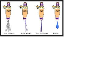
I think this is a good way to test injectors without pulling them right out. Doing all these tests you get a good estimation how well your injectors are working. If you get reading out of spec you can guess there maybe a bad connection somewhere. But pulling them out is also a good idea so you can put them on the pattern tester and see how well its spraying because you need good atomised spray not dribbles or uneven spraying. Atomised spray will give you a better combustion (bang) in the chamber than uneven spray or dribbles.

Input sensors & actuators ON-Vehicle

#1.0:
It is important to check voltage supply to the fuyel injector to make sure fuel is entering the cylinder. if theres lower voltage at the injectors than battery there maybe resisitance in the circuit or switching incorrectly or not at all.

#2.0:
The prpose of the reference voltage ot the throttle position sensor is to check power supply to sensor. Poor connection, bad earth, corrosion can all cause low reference voltage at the throttle position sensor.

#3.0:
The voltage on the earth side of the E.C.U is good. .03. It is important to measure so you know if the circuit is grounded and if its a good earth because you don't want a bad earth or high resistance beacause it might alter the signal voltage. Poor connections and corrosion could cause a bad earth.

#4.0:
When the T.P.S is at idle the voltage is low signal as the throttle opens voltage increases. (high signal) Closed throttle the sensor voltage should be 0v.66v. Open throttle the sensor voltage shoudl be .66v-5v.Bad connection in the potientcometer could prevent the T.P.S from sending the correct voltage to the ecu

#6.0:
And ECT sensor works when the engine is cold the voltage is high. As the engine heats up the voltageslowly decreases. when the ECT is cold it will send a high voltage signal to the injectors to richen up the mix because the engine isn't at operating temp yet. Faulty ECT sensor can cause incorrect voltage for the ECU.

#7.0:
The 0.03v reading tells us that the ECU earth is good because a bad earth connection could effect voltages in a series circuit. It is important to measure to check if the curcuit is complete and a good ground. Corrosion at the earth will cause a bad ground, even could break the ground and have an open circuit.

#4.0: (C.K.P)
The R.P.M sensor works as the speed increases the voltage increases a little bit. Using different functions are useful because they can tell you something other than voltage like how fast its working. A damaged sensor can effect signal voltage and also corrosion.

#5.0:
A map sensor works as the pressure in the manifold gets less the voltage drops. On idle voltage is high. pressure is high as you rev pressure decreases and so does the voltage. The reading are correct because the voltage is high on idle, low as you rev gthe engine. A cacuum leask can cause incorrect signal.

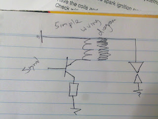
Building a simplified ignition module- off car

The information I got for the 2N2222 transistor was- max amps at collector= 600mA.
Max voltage 120volts

120 / 600mA = 200 ohms

V / A = R

The resistor I used was 200ohms in my curcuit for my ignition moduel.

I had trouble getting it to work beacuse I never earthed all components and also never powered the signal (base of transistor)

If I built the circuit again I would use a darlington pair. Next time Ill check that all components are powered earthed and all connected in a full curcuit.


Wiring up Ignition systems- off car


Testing Ballast Resistors- off car


Specs: 1.5ohms - 1.7ohms
Results: ballast resistor 1- 1.4ohms ballast resistor 2- 1.5ohms

To test ballast resistor set meter to ohms scale and place either side of the resistor.

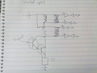
Wasted Spark Coil Pack- off car


Results: coil 1 & 2 secondary 6.9kohms
note- (couldn't test primary)

pin out- 1, 2, 3, 4, +, -, signal signal

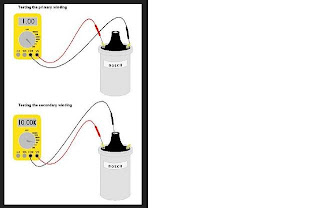
Testing ignition coils- off car


Results: COIL 1 primary windings- 2.8ohms
secondary windings- 9.35kohms
earth leakage- ol
COIL 2 primary- 1.2ohms
secondary- 8.77kohms
earth leakage- ol

note see picture to see how you place your multimeter.

Measuring current draw and Voltage drop:

Current draw- 3.60amps
Measured coil Voltage drop- 3.84volts
Measured ballast resistor voltage drop- 6.12volts

Calculated values: v/r = amps 12/ (2.8+ 1.4)= 3.75amps #2- 12/ (1.2+1.5)= 4.4amps

The first calculated result was good but the second calculated was not so good. Maybe the coil was too good with continuity giving low resistance

Injector testing- off car


Injector testing (INJECTORZ)
Fuel filter clogged, no fuel, bad earth can all relate as an injector not firing.
When removing injectors from engine take care to pull them out and don't clogg them.

TEST RESULTS: 4 injectors

Analysing results.
All injectors were quite good. Good spray patterns.

Optical distributor- off car


Optical distributor:
Results- position- 0, 90, 180, 270, 360degrees Voltage- 11.52, 0, 11.52, 0, 11.52

The difference between hall effect, optical & inductive signals? optical is a digital signal and goes from 0volts to a positive voltage (eg 12volts). A hall effect signal is analog and goes positive to negative (eg -12v to +12v). An inductive signal is the same as hall effects.

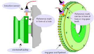
The degrees turned in a speed sensor to the degrees of crank shaft rotation is 540degrees to 720degrees

Hall effect sensor- off car

Results: Degrees turned- 45, 90, 135, 180, 225, 270, 315, 360. Voltage- 49.2, 2.9, 49.2, 2.9, 49.2, 2.9, 49.2, 2.9.

In the graph labeled point A- is when the distributor is passing through the window of the hall- effect point B- is when the hall is infront of the pickup. point C- that is 90degrees of turn and as u see it gone from one window and reached the other open window.

Speed or Position sensor- off car


electronic inductive distributor.

visual inspection was ok. tested ok. (cant find results) see video and youll see it works ok.

Magnetic distributor:

G pick up coil .203mm NE pick up coil .305mm both serviceable.

The waveform in the picture is analog signal. It goes positive to negative to positive. it stays the same shape but will get wider or narrow depending on the frequency

Oxygen sensor- off car

The output voltage of an oxygen sensor is high when there is no oxygen present. This is a lean mix. When the oxygen sensor is exposed to oxygen the voltage drops right off. This is a caused by a rich mixture. As the video showz

Knock sensor- off car

A knock sensor has peizo crystals and when preessure is supplied to it a voltage is created. The knock on the sensor creates the voltage output.

Air Temp Sensor- off car

A.,T.S (Air temperature sensor) Its a N.T.C thermistar. Meets specifications. They all have bio-metals and as they heat up the resistance decreases.
35degrees - 60 degrees
1.35 - 0.550

Thermo Fan switch- off car

Meets specifcations. ITs a N.T.C thermistar. It has bio-metals which bend at different rates. As the thermister heats up the resistance decreases.

Coolant Temp Sensor- off car

C.T.S (coolant temperature sensor) The C.T.S is a N.T.C thermister. As the coolant temperature sensor heats up the resistance decreases. The bio-metals inside bond at different temperatures.

20degress - 60 degrees

2.27 - 0.5

Air Flow Meter- off car


A.F.M (vane or flap air flow sensor) I tested a faulty 1. no results.

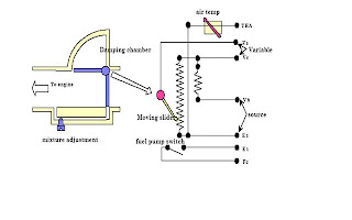
An air flow meter operates similar to an TPS. It has a potentiometer inside it and the swivel arm that attachs to the signal is hooked up to the flap piece that opens and closes. As the flap moves it moves the arm up and down the potentiometer (variable resistor) changing the output voltage depending on where it is on the potentiometer. The signal is sent to the ECU and tell it how much air flow is in the intake manifold.


MAF sensor- off car

MAF sensor (Mass Air Flow) 1.132v (No air flow) By blowing through it we get 3volts out of the signal. The results were within specifications. A M.A.F sensor works by, as air passes through the sensor the crystals change creating a high voltage output signal.

MAP sensor- off car

MAP Sensor - (manifold absolute pressure).A map sensor works as low vacuum is in the manifold a high output voltage of 5v. As vacuum is applied the output decreases depending on how much vacuum is applied.

TPS sEnsoR- off car

A TPS sensor is a variable resistor type. As the arm swivels on the variable resistor inside the resistance changes and causes the voltage across it to change as well which in turns changes the signal voltage output to.